

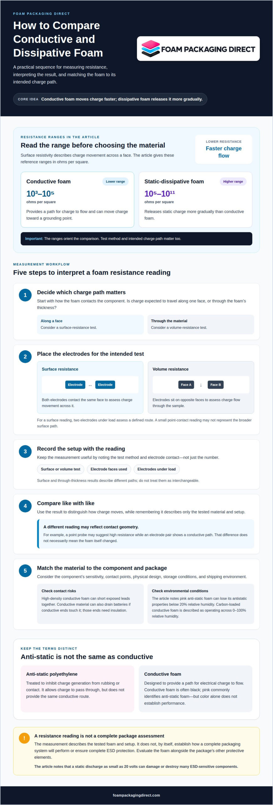
Conductive foam moves charge away faster because it has lower electrical resistance; dissipative foam releases charge more gradually. The conductive foam vs. dissipative foam surface resistivity comparison starts with their measured resistance ranges: conductive foam is described below 105 ohms per square, while static-dissipative foam is described from 105 to 1011 ohms per square. These ranges orient the comparison, but the test method and intended charge path matter too.
“Anti-static” is often treated as a single material category, but foam types manage electrical charge in different ways. The right choice depends on the component, how it contacts the foam, and the protection needed during storage or transit. This guide explains how anti-static foam works, how conductive and dissipative options differ, and what electrode-based measurements reveal about surface and volume resistivity. It also explains how to interpret a reading without mistaking it for a complete measure of package protection. Use these details to compare a foam’s stated properties with the packaging requirement and identify what to clarify before specifying a material.
Key Takeaways
- Match foam to the component’s sensitivity, surface, and shipping environment; color alone doesn’t establish its electrical behavior.
- Electrode placement matters: surface measurements use electrodes on one face, while volume measurements assess resistance through the material.
- Use resistance readings to distinguish how charge moves, then consider the packaging system as a whole when evaluating ESD protection.
- Compare material requirements with the applicable packaging standard, and choose foam inserts or other cushioning based on the product’s protection needs.
What is Conductive Foam?
Conductive foam is designed to provide a path for electrical charge to flow. Its surface resistivity is described in the range of 103 to 105 ohms per square. This electrical property helps charge move toward a grounding point instead of lingering on an electronic component. Conductive foam is often black, but color alone doesn’t establish its performance. A static discharge as small as 20 volts can damage or destroy many ESD-sensitive components, making material choice important during storage and transit.
Start by considering the component’s sensitivity and physical design. An exposed circuit board may need cushioning that controls movement while limiting static risks. Exposed leads create a different contact concern: high-density conductive foam can short pins together, preventing a potential difference between them. Product weight, fragility, surface sensitivity, and shipping conditions also influence the cushioning choice. A delicate board, for example, may need a fitted cavity to prevent shifting, while a heavier assembly needs support suited to its load. Foam cushions against impact and movement, but its electrical properties address charge behavior, not every packaging risk.
Compare conductive foam with anti-static foam by how each manages charge. Anti-static polyethylene is treated to inhibit charge generation from rubbing or contact. It allows charge to pass through, but doesn’t provide the same conductive route. Pink coloring commonly identifies anti-static foam; black often identifies carbon-loaded conductive foam. Neither color replaces a resistance measurement. Environment matters, too: pink anti-static foam can lose its antistatic properties below 20 percent relative humidity, while carbon-loaded conductive foam operates across 0 to 100 percent relative humidity.
For transit cushioning, low-density conductive foam can protect sensitive components such as circuit boards or hard disk drives. For leaded components, high-density foam may help keep pins at a common electrical potential, provided the pin contact suits the component. Consider what the foam touches, too: conductive material can drain batteries if their conductive ends contact it, so those ends need insulation. Anti-static cushioning and conductive foam have distinct roles, and neither alone ensures complete ESD protection. Choose based on component sensitivity, contact points, storage conditions, and the package’s overall protection needs.
Electrode-based resistance measurement
An electrode-based measurement shows how readily charge moves through or across a foam sample. To measure surface resistance, a meter measures resistance between two electrodes placed under load on the same face. The reading helps distinguish materials that conduct charge from those that resist its movement. A meter can help determine a foam’s resistivity level, but the result describes only the tested material and setup. On its own, it does not establish how a complete packaging system will perform around a circuit or during a static discharge.
Electrode contact matters. A point-contact reading may appear insulative even when the tested part is conductive, because a small contact area may not represent the broader surface path. By contrast, two electrodes under load assess a defined route across the material. This distinction is useful when carbon-loaded foam appears conductive by composition but a spot measurement gives a different impression. Consider the measurement method alongside the value rather than assuming every meter reading is directly comparable.
Surface and volume tests answer different questions. For surface resistance, both electrodes contact one face, showing how charge can travel along that face toward a ground connection. For volume resistance, electrodes sit on opposite faces of the sample to measure charge flow through its thickness. A square-based surface value describes the material’s surface behavior; it is not interchangeable with a through-thickness result. Use the test that matches the intended contact path in the packaging design.
For example, evaluate a foam layer touching a component across its surface if that is the relevant contact path. If the design relies on charge moving through the foam, use a volume measurement. Record which faces contact the electrodes and whether they were placed under load. Then compare like with like when reviewing conductive and static-dissipative material properties. If a point probe suggests high resistance but an electrode pair shows a conductive path, the difference may reflect contact geometry, not a change in the foam. That context makes the measurement more useful for material selection.
Conductive foam surface and volume resistivity
Surface and volume resistivity describe different paths for charge through foam. The conductive foam vs dissipative foam surface resistivity comparison helps distinguish charge movement along a face from movement through the material.
Surface Resistivity
Surface resistivity measures how strongly foam resists charge moving across its outer face. Conductive foam is described at 103 to 105 ohms per square, while static-dissipative foam spans 105 to 1011 ohms/square. The lower range indicates a more conductive surface, while dissipative material releases static charges more slowly.
This difference matters when a device contacts foam along a surface path. A lower-resistance path can move charge toward ground more readily, while a dissipative path controls that movement. Surface resistance alone does not prove that a package provides shielding or prevents every electrostatic discharge. Evaluate the foam’s role alongside the package’s other protective elements.
Volume Resistivity
Volume resistivity measures resistance to charge moving through the foam’s thickness. Conductive ESD foam typically has volume resistivity below 104 ohms per centimeter, while anti-static foam typically ranges from 1010 to 1012 ohms per centimeter. These values describe through-material behavior, not movement along the surface.
That distinction helps match a test to the packaging design. If a charge path runs from one foam face to the opposite face, volume resistivity is relevant. For example, assess a foam layer separating a component from a conductive support through its thickness. A surface reading cannot replace that measurement.
Read both values in context. A conductive surface result does not establish the foam’s volume behavior, and a volume result does not describe how charge travels across the face. Units matter, too: ohms per square apply to surface resistivity, while ohms per centimeter apply to the listed volume-resistivity values. Do not compare the figures as if they measured the same property.
For selection, identify the intended contact and charge path, then compare the matching resistance property. Conductive materials provide a faster route for static charges; dissipative foam manages their movement more slowly. A conductive foam vs dissipative foam surface resistivity comparison is useful only when the measured property matches the package’s intended charge path. Neither reading alone confirms that the complete package prevents electrostatic discharge or provides shielding. Assess the foam as one part of the packaging system, considering the device, contact points, and required protection.
What standards classify conductive and dissipative packaging materials?
ESD standards address different parts of packaging and control programs. Their scope matters because a foam resistance value alone doesn’t establish that a complete package meets a standard. ANSI/ESD S20.20 addresses electrostatic discharge control programs, while EIA-541 concerns packaging materials for ESD-sensitive items. EN 61340-5-1 and IEC 61340-5-1 are also standards to consider when selecting foam.
Match the reference to the requirement it covers. A control program, packaging material, and broader handling system are separate concerns. Consider a material classification alongside its test method and intended application. For example, a packaging specification focused on material resistance calls for a relevant material measurement, while a program requirement may cover more than the foam alone.
Conductive thresholds can vary across classifications. Conductive materials are described as having surface resistance below 1 × 10⁵ ohms per square, while another classification places conductive foam below 1.0 × 10⁴ ohms. Treat these values as classification-specific, not interchangeable pass limits. Compare the required category, measurement method, and units together. Surface resistance and volume resistivity describe different paths, so one result cannot replace the other.
Contract references may add material-specific requirements. MIL-PRF-81705 is identified as a performance-criteria reference for military, defense, and aerospace packaging contracts. MIL-PRF-26514 covers cushioning polyurethane foams, a different concern from conductive or dissipative classification. For a shipping design, identify the applicable contract or program requirement, then select a foam and test property that address it.
Standards guide material selection, but foam is not the entire protection system. The box, shielding, closure, and handling process also affect ESD protection. Dissipative material manages charge differently from conductive material, so the specification should identify the required category and test property. Align those details with component contact points and packaging use before finalizing a material choice.
Foam Packaging Direct: Custom Foam Inserts
Foam Packaging Direct helps translate component and ESD packaging requirements into a practical foam design. Custom foam inserts organize parts and limit movement, while conductive foam packaging serves applications requiring conductive material. Foam sheets and pads, or foam rolls and wrap, can suit other cushioning layouts.
Consider an insert when components need separate cavities, stable positioning, or protection around specific contact points. Share the product’s dimensions, weight, quantity, shipping ZIP code, and any drawings or photos. Include existing box dimensions and special protection requirements so the packaging can be considered as a complete application, not just a foam material choice.
Turn the Material Choice Into a Packaging Plan
The next step is to connect the resistance requirement to the product’s actual packing conditions. Consider how each component sits in the package, which surfaces touch the foam, and how the product is handled during storage and transit. This application-level view makes the difference between conductive and dissipative foam surface resistivity useful for a packaging decision, rather than merely a material comparison.
Foam Packaging Direct offers custom foam inserts, foam end caps, and foam sheets and pads for different protective layouts. Share your product dimensions, weight, order quantity, shipping ZIP code, existing box dimensions, and any drawings or photos. Include the ESD requirement and any special protection needs so the packaging can be considered around the part and its use.
Request a quote from Foam Packaging Direct to move your packaging plan forward with clear project details.
Frequently Asked Questions
Static Dissipative vs Conductive: What is the Difference?
The practical difference is how each material fits the charge-control design. A conductive material suits a package designed around a defined path to ground; a dissipative material suits controlled charge movement around sensitive parts. Before choosing, map where the component touches the foam and whether the package includes a grounding path. Those details help make the material category meaningful for the application.
What does conductive mean?
Conductive describes a material that lets electrical charge move through it. For packaging, consider whether the foam contacts exposed electrical points or another conductive surface. A meter reading describes resistance between test contacts, but it does not establish the complete package’s function. Compare the material’s test result with the intended contact arrangement and packaging specification.
What resistivity range is suitable for ESD protection?
No single resistivity range suits every ESD application. The required value depends on the packaging specification, component exposure, and the charge path the design needs to manage. Start with the stated material category and test property, then check that the result uses matching units and a relevant measurement method. Also account for the box and other protective packaging elements.
What is the difference between conductive and dissipative foam?
Conductive and dissipative foams serve different charge-management roles, so choose according to the package design rather than color or label alone. A component with exposed electrical contacts, for example, may need a different arrangement from one separated from the foam by an insulating layer. Review contact points, the package’s grounding plan, and the component’s handling needs together before specifying a foam category.
What surface resistivity range defines conductive foam?
There is no universal cutoff used in every classification. The applicable specification defines the required conductive category and its surface-resistance threshold. Check that the documented value is a surface measurement, then compare it with the reference named in the packaging requirement. This avoids treating a threshold from one classification as a pass limit for another material specification or test method.
What surface resistivity range defines dissipative foam?
The defining range depends on the classification or specification being applied. Use the threshold stated in that reference, and confirm that the result describes surface resistance rather than resistance through the foam’s thickness. If documents give different boundaries, follow the requirement governing the package and compare values measured using compatible methods. This keeps the material designation tied to the actual application.