
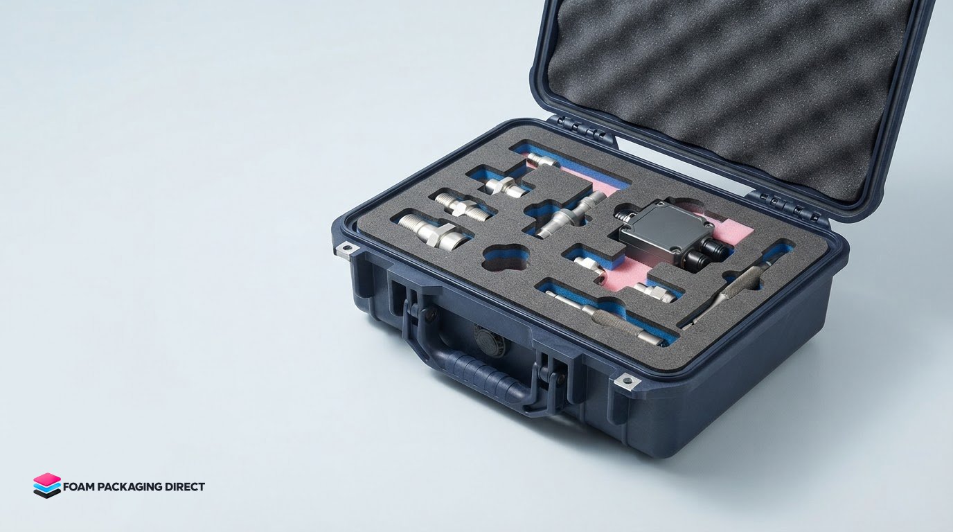
Aerospace parts need more than a cavity that matches their outline. Foam inserts for aerospace parts are designed around each component’s shape, support points, contact surfaces, and how it is placed in and removed from its package. Precision cutting and routing can create pockets at different depths to hold parts in a defined orientation.
A precise fit matters when components have specific handling needs or must stay organized alongside tools and other parts. The insert should also fit the outer box or case and suit the way people pack and access its contents.
This article explains how to plan an insert, choose a suitable foam and packaging format, and prepare for fabrication. You’ll see how cavity layout, material selection, and packing sequence work together, so you can define what the package needs to protect and provide clear details when requesting a quote.
Key Takeaways
- Plan cavity shape, support points, and removal sequence around each component and how it will be packed.
- See how a reported 72-inch drop test involving F-18 replacement parts illustrates the role of protective insert design.
- Understand when CNC-routed, closed-cell cross-linked polyethylene may suit a packaging layout, including cavities with varied depths.
- Compare inserts, end caps, and foam pads to find a format that fits the part, outer package, and handling process.
How are custom foam inserts designed for aerospace components?
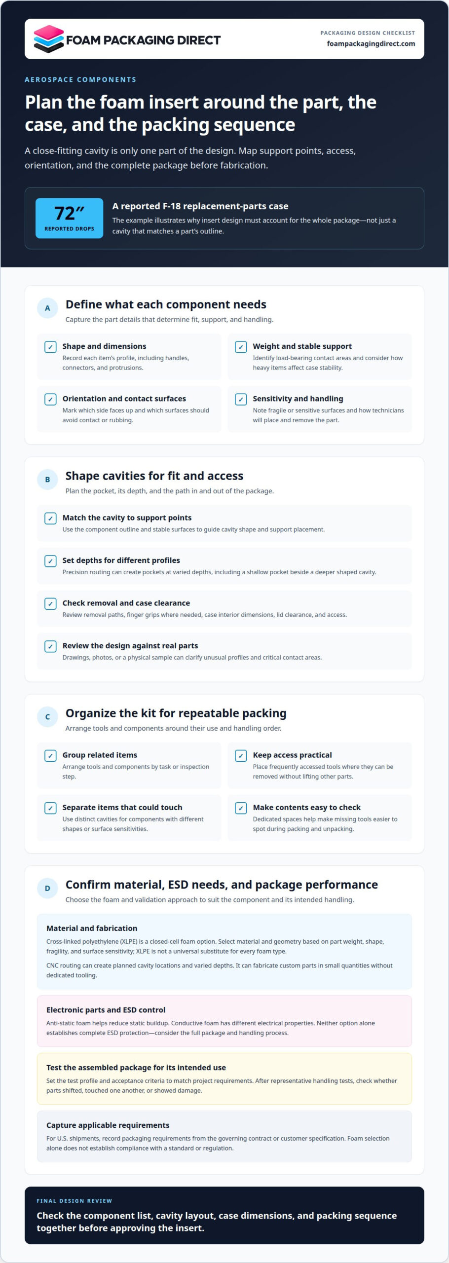
Start with the component’s shape, weight, contact surfaces, and required orientation. Then account for how technicians will place, remove, and transport each item.
Custom Inserts for Protective Cases
For a protective case, map each cavity to the component’s outline, support points, and removal path. Precision routing can create cavities at different depths for parts with varied profiles. Check the case’s interior dimensions, lid clearance, access, and packing sequence before finalizing the layout.
A reported case for F-18 fighter-jet replacement parts involved drops from 72 inches. The example highlights why insert design must account for the whole package, not just a close-fitting cavity. For specialized tooling or heavy equipment, identify load-bearing contact areas and limit unwanted movement. Transit risks can include impacts, vibration, and shifting inside the case.
Evaluate vibration, shock, and transit protection by testing the assembled package under handling conditions that represent its intended use. Check whether parts shift, touch one another, or show damage afterward. Set the test profile and acceptance criteria to match the project’s requirements.
ESD, Standards, and Material Risks
For electronic aerospace parts, choose an ESD-control approach suited to the component and packaging system. Anti-Static Foam helps reduce static buildup, while Conductive Foam has different electrical properties. Neither option alone establishes complete ESD protection, so account for the full package and handling process.
For U.S. shipments, capture applicable packaging requirements from the governing contract or customer specification. Foam selection alone does not establish compliance with a standard or regulation. For contamination or corrosion concerns, review contact points, cleanliness needs, and moisture exposure. Keep sensitive surfaces from rubbing against cavities, and define inspection steps for packing and unpacking.
Custom foam inserts for aerospace tools and components
A well-planned insert turns a mixed tool set into a clear, repeatable packing layout. Start by listing the tools and components that travel together, such as inspection gauges, hand tools, sensor housings, or machined brackets. Record each item’s dimensions, weight, surface sensitivity, and required orientation. These details help define cavity shapes and support areas.
Arrange the items according to their use and handling sequence. Place frequently accessed tools where a technician can remove them without lifting other parts. Separate metal components that could contact or scratch one another. A dedicated cavity for each item also makes missing tools easier to spot during packing and unpacking.
For mixed aerospace kits, distinguish parts by shape and handling needs rather than forcing every item into the same cavity style. A long tool may need a channel that supports its length. A small component may fit a compact pocket, while a delicate surface may call for a layout that limits direct contact. Leave room for fingers or a removal grip when the packing process requires it.
- Group related tools by task or inspection step.
- Position heavy items so the packed case stays stable during handling.
- Use separate cavities for components with different shapes or surface sensitivities.
- Compare the proposed layout with the actual case interior and packing sequence.
Drawings, photos, and a physical sample can help communicate unusual profiles or protrusions. Mark critical contact areas and show which side must face upward. For a kit that changes over time, identify which cavities should remain fixed and which may need revision. This helps keep the insert useful as the component set evolves.
For foam inserts for aerospace parts, the best layout matches the actual kit, not an assumed standard arrangement. Review the component list, case dimensions, and removal order together before approving the design.
CNC-routed closed-cell, cross-linked polyethylene foam
Routing and Cross-linked Polyethylene (XLPE) Foam address two different design decisions: how to shape an insert and which foam to use. Match both choices to the component and package.
CNC-Routed Foam Inserts
Precision routing uses computer-guided tools to cut foam to a planned shape. For an aerospace case, it can create cavities at multiple depths for parts with different profiles. This approach can fabricate custom parts in small quantities without dedicated tooling. The design file guides cavity placement, depth, and the overall insert outline.
Before routing, define the case interior, part dimensions, and cavity locations. Mark features such as handles, connectors, or protrusions that affect how each component sits. Then review the cut layout against the actual parts and package. For example, a shallow pocket can keep a flat item distinct from a deeper cavity shaped for a component with a projecting feature.
Closed-Cell Cross-Linked Polyethylene
Cross-linked Polyethylene (XLPE) Foam has an enclosed-cell structure. Choose the material based on the aerospace part’s weight, shape, fragility, and surface sensitivity. These factors guide how much of the part contacts the foam and where the insert provides support. XLPE is one option, not a universal substitute for every foam type.
Specify the intended use alongside the part drawing. Include dimensions, orientation, and any areas that should avoid contact. For an irregular housing, for instance, the design can align cavities with stable surfaces rather than resting the part on a connector. Confirm that the selected foam thickness and routed geometry fit the case and packing method. A clear specification helps align material selection with the insert’s intended function.
What types of foam inserts are used to package aerospace parts?
The right insert format depends on the part, outer package, and packing sequence. A shaped insert, layered pads, end caps, or a foam-lined container can each support a different arrangement.
A shaped insert holds a component in a defined orientation. Cavities can separate several items in one case, such as a sensor housing and its related tools. Plan cavity shape, support locations, access, and removal order together. Precision routing can create multiple cavity depths when parts in the same case have different profiles.
Foam pads suit packages that separate or layer items instead of holding each one in an individual pocket. Place them to protect contact surfaces and match the order in which packers stack components. For example, a pad between two flat assemblies can limit direct contact while keeping the package layout simple.
Foam End Caps provide localized support at a component’s ends. They can suit a long part when its ends offer suitable contact areas. Shape the caps around those areas, then consider how they will stay positioned during handling. A foam-lined box or crate integrates cushioning with the container, so its interior layout, dimensions, access, and workflow all matter.
- Choose shaped cavities for parts that need a set orientation or separate positions.
- Use pads when the packing sequence relies on layers or separators.
- Consider end caps when support at the component ends fits the geometry.
- Plan a foam-lined container around its interior space and handling process.
Material selection is another decision. Polyethylene (PE) Foam and Cross-linked Polyethylene (XLPE) Foam are options for shaped inserts; Polyurethane (PU) Foam, Expanded Polystyrene (EPS) Foam, and Expanded Polypropylene (EPP) Foam may suit other packaging formats and needs. Compare the part’s weight, fragility, dimensions, surface sensitivity, and shipping conditions before choosing. Anti-Static Foam may suit static-sensitive components, but it does not by itself make a complete package ESD compliant.
Share the part dimensions, weight, quantity, and package layout when you request a quote for aerospace packaging.
Foam Packaging Direct: Custom Foam Inserts
Foam Packaging Direct supplies custom foam inserts for aerospace components and related packaging needs. Foam end caps can support component ends, while foam sheets and pads can separate items or add cushioning inside an existing package. Foam Packaging Direct serves businesses nationwide, with manufacturing capabilities across the country. Regional production can help reduce freight expenses and turnaround times.
Consider a custom insert when parts need defined positions, organized storage, or repeatable packing. For a quote, provide product dimensions, weight, quantity, shipping ZIP code, and available drawings or photos. Include existing box dimensions and special protection requirements when relevant.
Request a quote from Foam Packaging Direct to discuss your packaging requirements.
Put the packaging specification into action
A useful next step is to turn the component’s handling needs into a clear packaging specification. Record the part’s orientation, contact-sensitive surfaces, and any features that need clearance. Include the case or box’s interior dimensions so the insert layout can be designed alongside the outer package. For foam inserts for aerospace parts, these details connect the design intent to the way parts are packed and accessed.
Foam Packaging Direct offers custom foam inserts, foam end caps, and foam sheets and pads for different packaging layouts. To start a project, provide product dimensions, weight, quantity, shipping ZIP code, and any available drawings or photos. Add existing box dimensions and special protection requirements when they apply.
Contact Foam Packaging Direct to discuss your packaging requirements and take the next step toward a package designed around your parts.
Frequently Asked Questions
How should material selection reflect component requirements?
Choose foam by balancing part weight, edge shape, fragility, surface finish, and reuse needs. Polyethylene (PE) Foam suits heavy or sharp-edged parts, while Cross-linked Polyethylene (XLPE) Foam suits clean, premium finishes. Polyurethane (PU) Foam can work for delicate, lightweight items. For example, a reusable transport container may suit Expanded Polypropylene (EPP) Foam. Match the material to the whole application, not just one feature.
What information is needed for an aerospace foam insert quote?
Provide the part’s dimensions and weight, the box or carton size, order quantity, and any drawings or photos. Include details that affect the layout, such as connector locations, delicate surfaces, or required orientation. If a drawing is unavailable, a product sample can be shipped for measurement. These details help define the insert around both the component and its container.
What should a packaging specification capture?
Record the component’s dimensions, weight, orientation, and areas that should avoid contact. Include the container’s interior dimensions and explain how parts are arranged together, such as a sensor beside its cable or accessories. Note the required material and any static-control needs. A dated drawing or photo set can distinguish the current design from earlier revisions and keep production instructions clear.
What transit risks should an aerospace packaging brief identify?
Describe the handling and shipping conditions the package may encounter, including impact, vibration, and changes in orientation. Identify whether parts travel together or separately, and flag protrusions or fragile interfaces that could contact nearby items. For example, a connector extending from a housing may need clearance during movement. Explain how the component is packed and removed so the insert supports the full handling sequence.
Which foam materials meet aerospace packaging requirements for shock absorption and cleanliness?
No single foam suits every shock or cleanliness requirement. PE, XLPE, PU, EPS, and EPP each serve different packaging applications, so selection should follow the component’s weight, fragility, surface, and handling needs. XLPE may suit parts requiring a clean, premium finish; PU can suit delicate, lightweight items. For static-sensitive electronics, anti-static foam is an option, but it does not alone provide complete ESD protection.
How do you design custom foam inserts for aerospace components?
Start with part and container dimensions, then define cavity shape, depth, orientation, contact areas, and removal access. The design can be cut to the required pocket shapes and depths, then reviewed as a sample before production approval. For repeat orders, Foam Packaging Direct keeps designs on file to support consistent reorders. Drawings, photos, or a physical sample can help communicate unusual part features.