
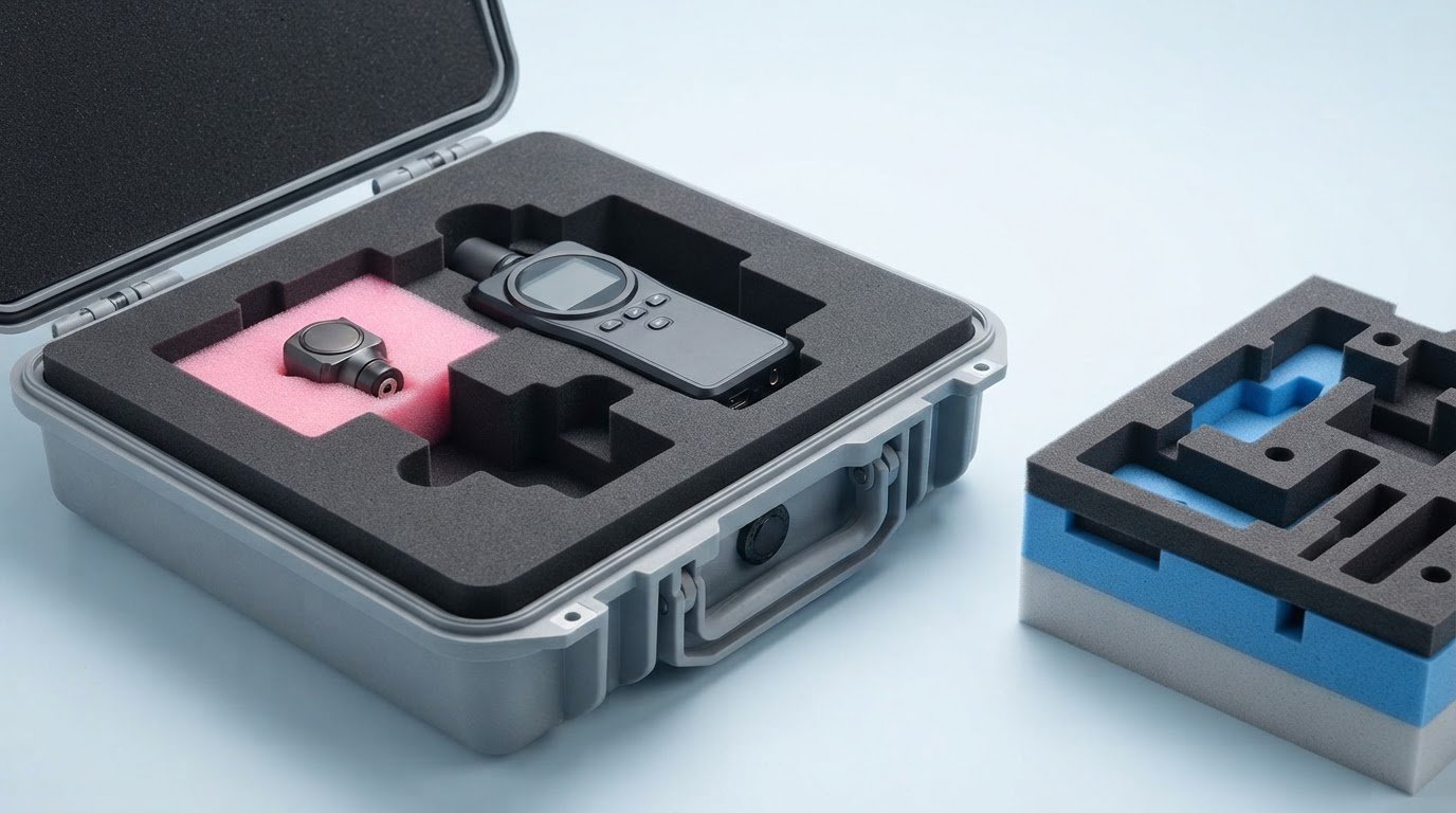
A CAD model can look complete and still conceal a fit or geometry issue. Custom foam prototyping turns a digital design into a physical model that teams can inspect for scale, shape, and how parts fit together before production.
An early physical check makes design discussions more concrete. Engineers and decision-makers can handle, compare, and refine a foam sample instead of relying on a screen alone.
This article explains what foam prototyping and modeling involve, how prototypes support different applications, and how density and geometry can be adjusted and evaluated. It also covers how material and fabrication choices relate to the questions your sample needs to answer.
Key Takeaways
- Use a physical foam model to assess a design’s scale, shape, and fit before moving toward production.
- Plan prototype tests around the questions that matter, such as fit, handling, or performance in intended conditions.
- Consider how foam density and geometry affect a model’s behavior, then use testing to guide refinements.
- Compare fabrication approaches and share product details, drawings, or photos when requesting a quote for protective foam packaging.
What is Foam Prototyping & Foam Modeling?
Custom foam prototyping turns a product concept or CAD design into a physical model. Inventors and product teams can handle it to assess scale, shape, and component relationships. This review may reveal a clearance problem or awkward assembly that looked acceptable on screen. Teams can then revise the geometry before production decisions become harder to change.
Models can represent a small component, a full product, or a large structure built from machined foam pieces joined together. For example, an OEM can use a housing model to check how components meet and where access is needed. Polyurethane tooling board comes in material formulations suited to different machining and temperature needs. A specialized low-CTE, high-temperature polyurethane tooling foam has a density of 48 lbs/ft³.
Prototyping can also clarify assembly steps. When a foam part is designed to fit an assembly, the team can assess whether its shape reduces the need for secondary cutting, fasteners, or stacked layers. Review how workers position the part and access adjoining components. This helps teams discuss production readiness, although a model alone does not establish full manufacturing performance.
To request a prototype, provide product dimensions, intended use, material preferences, and any available CAD files or drawings. Photos, assembly views, and notes about critical clearances can clarify which features the model needs to represent.
Lead time depends on file readiness, geometry, material, and fabrication steps. Minimum quantity depends on whether the project requires a single design sample or repeated prototypes for comparison and revision.
To choose a nearby prototyping company, compare its ability to work from CAD data, machine the required geometry, and discuss suitable tooling materials. Ask how the review process will cover your design’s fit and assembly questions.
A foam model is a design aid, not proof that a production part will perform identically. Define what the prototype needs to demonstrate, and follow material-specific shop handling procedures during fabrication and review.
Prototype samples and testing
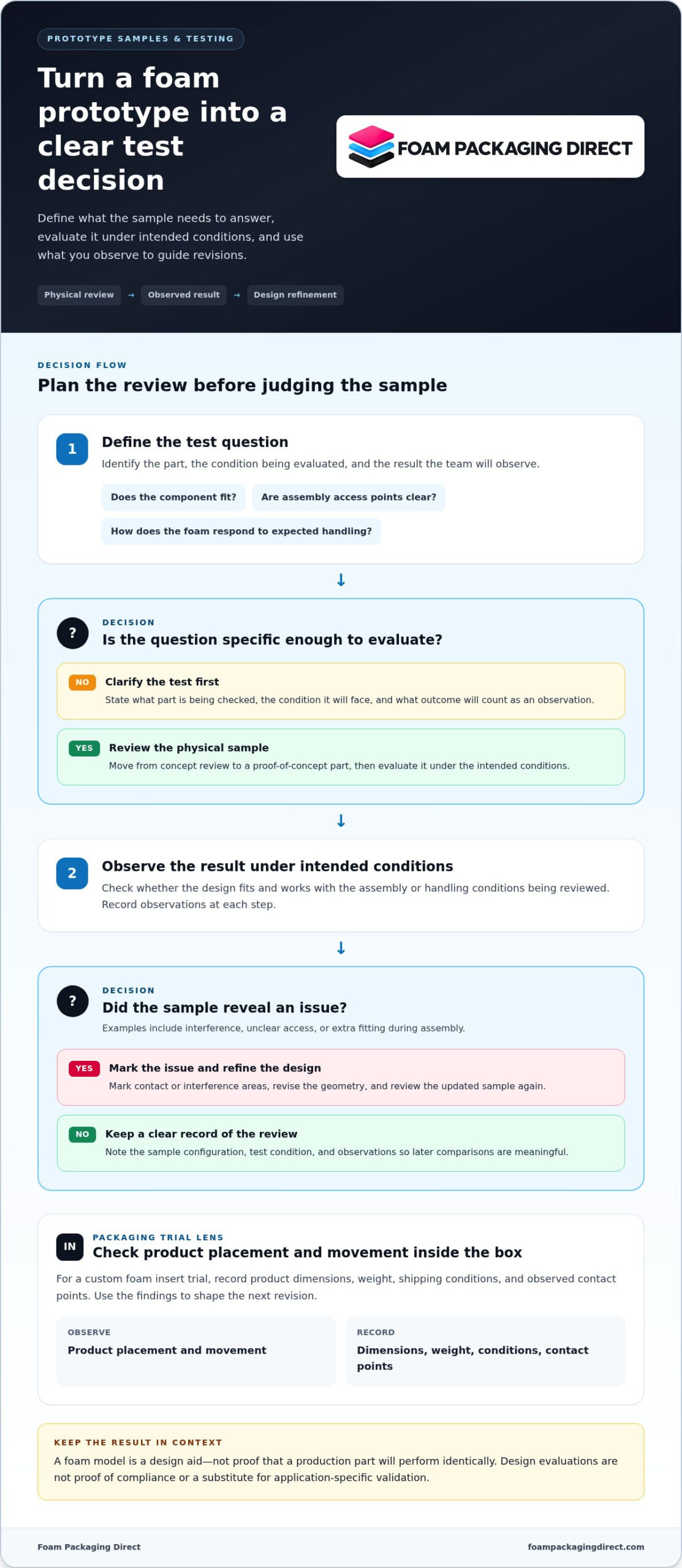
A prototype gives a development team a physical part to evaluate before committing to production tooling. Testing can reveal fit or performance issues while the design is still open to revision. For example, an equipment team can check whether a component seats correctly inside its housing and whether access points remain clear during assembly.
Start by defining what the sample needs to answer. A useful test plan identifies the part, the condition being evaluated, and the result the team will observe. For a protective enclosure, that might mean checking component fit, assembly access, or how the foam responds to expected handling. Clear criteria make feedback easier to turn into specific design changes.
A practical development sequence moves from concept review to a proof-of-concept part, then to tests under intended conditions. Record observations at each step. If a sample interferes with a nearby component, mark the contact area and revise the geometry. If workers need extra fitting or fastening, consider whether the design better reflects the actual assembly process. This helps teams compare the prototype with real production conditions.
Testing should match the intended application. An industrial component may need checks focused on fit and assembly, while a medical manufacturing project may examine how a model aligns with design requirements. A molded foam prototype can also help teams assess insulation effects or thermal buildup. These are design evaluations, not proof of compliance or a substitute for application-specific validation.
Flat, die-cut materials may require cutting, fitting, fastening, or retrofitting during development. Those extra operations can slow revisions and create differences between samples. A formed prototype can help teams evaluate a more integrated geometry. For packaging trials, a custom foam insert can help assess product placement and movement inside a box. Record product dimensions, weight, shipping conditions, and observed contact points so the next revision addresses the test findings.
Tunable foam density and geometry
Density and geometry give engineers two practical ways to shape a foam prototype’s behavior. Density describes how much material occupies a given volume; geometry includes its form, thickness, openings, and contact surfaces. In molded polyurethane foam, adjusting density and geometry can help target acoustic performance. The right combination depends on the function being evaluated, not density alone.
For example, a prototype designed to manage sound can compare different wall thicknesses, cavities, and openings. The foam’s cellular structure and thermal conductivity also affect its behavior, so changing density may alter more than weight or firmness. Record each design version, material, and test condition to identify which change affected the result.
A controlled comparison can follow a simple sequence:
- Set the performance question, such as how a panel changes sound transmission.
- Choose the geometry features to evaluate, such as a cavity, channel, or curved surface.
- Vary one design factor at a time where practical, and record the sample configuration.
- Test each sample under the same conditions, then use observations to guide revisions.
Geometry can also be tailored to an assembly. A shaped recess may position a component, while a channel can preserve clearance for a cable or moving part. These features help reveal whether the design fits its intended space and whether adjoining parts interfere. Evaluate density and geometry together when both affect the prototype’s function.
After machining, a model can remain raw or receive a hard coating and paint if the review requires a finished surface. Surface treatment affects what teams can inspect visually and by touch, but it does not replace functional testing. Record the finish alongside the foam and geometry to make later comparisons useful. For each revision, retain the CAD version and note the changed feature, the reason for the change, and the observed outcome.
What custom foam prototyping methods are available, such as CNC cutting, routing, and molding?
Most foam prototypes are CNC machined from CAD data on a router. The programmed cutting path shapes the material into the contours, cavities, and openings in the design. This method suits a housing model with detailed pockets or a large form assembled from several machined pieces. A clean CAD file helps translate the intended geometry into a physical sample.
Material choice affects how a prototype can be made and what it can demonstrate. EPS, EPP, polyethylene, and urethane tooling foam are among the materials used for machining. They are not interchangeable: each has different properties and suitability for particular applications. Choose based on the model’s purpose, the required geometry, and whether the sample represents packaging, a component, or a larger shape.
Other approaches can suit different design questions:
- CNC cutting and routing: Machine a CAD-based shape from foam stock to evaluate contours, fit, or scale.
- Die cutting: Cut flat material into repeatable outlines, useful for simple layers or pads.
- Molding: Form foam into a designed shape when the part’s geometry and intended use call for a molded structure.
Start by identifying what the prototype must prove. A routed sample can show whether a component fits a cavity. A die-cut layer can test a flat profile, while a molded sample can help assess a shaped part. The design’s complexity, material, and evaluation goal guide the method. For a large model, machining and joining separate sections can create a complete form.
Share CAD files or dimensioned drawings, and mark critical surfaces, clearances, and features that must appear in the sample. Include the selected foam material, if known, and the prototype’s intended use. These details help match the machining approach to the design review. If the model represents protective packaging, include product dimensions and existing box measurements so the sample reflects the available space.
Foam Packaging Direct: Custom Foam Inserts
Foam Packaging Direct helps turn packaging requirements into practical protective foam solutions. After evaluating a product model, teams can apply those design insights to packaging that holds components in position, limits movement, and supports consistent packing.
Custom foam inserts suit products that need shaped compartments, while foam sheets and pads can separate or cushion surfaces. Foam rolls and wrap provide flexible cushioning, and tote and tray inserts can organize components for handling or storage. The right format depends on product dimensions, weight, fragility, surface sensitivity, shipping conditions, and order quantity.
Request a quote with your product dimensions, weight, quantity, shipping ZIP code, and any available drawings or photos. Include existing box dimensions and special protection requirements that affect the design.
Carry Prototype Learning Into Your Packaging Plan
A prototype review can clarify how the finished product should be protected, positioned, and packed. Use what your team learned about fit and contact points to set packaging priorities, such as limiting movement, separating components, or cushioning exposed edges. The package design can then reflect the product’s actual shape and handling needs.
Foam Packaging Direct offers custom foam inserts, foam end caps, and foam sheets and pads for different protective packaging needs. For a quote, prepare product dimensions, weight, order quantity, shipping ZIP code, and available drawings or photos. Existing box dimensions and specific protection concerns can clarify how the package needs to work. These details also provide a practical starting point for discussing how custom foam prototyping findings can inform your packaging choice.
Share your packaging requirements with Foam Packaging Direct, and take the next step with a clearer direction for your product.
Frequently Asked Questions
What is custom foam prototyping and what is it used for?
It is the creation of a physical foam sample to evaluate a product or packaging concept. Beyond checking general fit, teams can use a sample as a shared reference during design reviews, compare alternate component layouts, or show stakeholders how a product occupies space. For example, a layout model can help a team decide where separate parts should sit before packaging drawings are finalized.
Which foam materials are used for custom prototypes, and how do they compare?
Common options include polyethylene, XLPE, polyurethane, EPS, and EPP, but their cushioning behavior differs. PE and XLPE are often considered for firmer protective applications, while polyurethane can suit softer cushioning needs. EPS and EPP are expanded materials with distinct handling and performance characteristics. Anti-static cushioning for sensitive electronics can help reduce static charge buildup, but it is not a substitute for a complete ESD protection plan.
What tolerances, densities, and finishes can foam prototypes achieve?
Tolerances depend on the material, part size, geometry, and machining process. For a useful quote or drawing review, mark critical dimensions and identify the surfaces that must align with adjoining parts. Specify whether the sample is for visual review or dimensional evaluation. That distinction helps set practical expectations for measurement and finish without applying one tolerance to every foam part.
How can I test a foam prototype for fit, durability, and performance?
Set acceptance criteria before testing, such as whether a component remains seated after repeated removal or whether the foam shows visible damage after handling. Record the sample version and observations so the team can compare revisions consistently. To discuss a packaging quote, send product dimensions, weight, quantity, shipping ZIP code, and available drawings or photos.